Documentation Index
Fetch the complete documentation index at: https://docs.flexwash.com/llms.txt
Use this file to discover all available pages before exploring further.
We have a network integration with Elka and Magnetic MGC-PRO gates with their ethernet modules. All other gates require this Relay integration.
Work with a licensed electrician when wiring gates. Incorrect wiring can damage equipment or cause injury/death.Make sure to read all manuals from the gate manufacturer and Moxa carefully.
 We recommend you mount this unit on a din rail in a climate controlled environment.
Relay Output Wiring
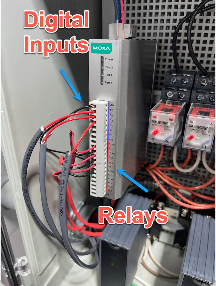
We open the gate by wiring up two wires into a relay on the E1214.
You should test this by manually connecting these two wires and confirming the gate opens.
We use digital inputs to detect when the gate is closed and when the induction loop is occupied.
The E1214 supports two wiring methods: dry contact and wet contact (NPN). We strongly recommend dry contact wiring when your gate supports it.
Dry contact wiring is electrically isolated and requires no external power supply. This makes it safer and simpler to install.
 There should be no voltage across the two terminals. But you should see some connectivity when the gate is closed. Make sure to confirm both with a multimeter before wiring to the E1214.
Connections:
There should be no voltage across the two terminals. But you should see some connectivity when the gate is closed. Make sure to confirm both with a multimeter before wiring to the E1214.
Connections:
- DI0 → Gate switch terminal
- GND → Gate switch terminal
- COM 0 → Not used
How it works:
- Switch closed → DI0 shorted to GND → Moxa reads ON
- Switch open → Moxa reads OFF
Use NPN wiring when the gate outputs an active signal rather than a passive switch closure. This requires an external 10-30V DC power supply.
 Make sure the voltage and current is within the E1214’s tolerance before wiring it up.
Connections:
Make sure the voltage and current is within the E1214’s tolerance before wiring it up.
Connections:
- COM 0 → DC power (+)
- DI0 → Gate black wire (output)
- GND → DC power (−)
- Gate brown wire (+V) → DC power (+)
- Gate blue wire (GND) → DC power (−)
How it works:
- Sensor idle → Black floats high (10-30V across DI0↔COM) → Moxa reads OFF
- Sensor triggered → Black sinks to GND (0-3V across DI0↔COM) → Moxa reads ON
Multiple Channels
The E1214 has 6 digital input channels (DI0–DI5). Each channel can monitor a separate gate. Wire additional gates to DI1, DI2, etc. using the same method.
Vendor Specific Instructions
Giotto
Programming
- Top button is ”+”.
- Below it is ”-”.
- Below that is “OK”.
- To exit from the current menu, press BOTH ”+” and ”-” AT THE SAME TIME, then immediately release.
Start by pressing "OK" once -> screen should read "LANG", then show current language setting
  Language setting should be "EnG". If it is not, use +/- to scroll to "EnG", then press "OK"
  After changing the language setting, or if language is already correct, exit menu until you're back at the main screen
	DO NOT continue pressing "OK" after selecting the language
Next, configure the gate logic settings
	Press "OK" twice in rapid succession
	You should see "hALT" or "ALT" appear on the screen. Press "OK"
	You should see something like "FoLLoW thE USEr GUIdE" scroll across the screen. Press "OK" to skip
	You should see "PArAM" appear on the screen. Use +/- to navigate down to "LoGIc" and press "OK"
	We are now in the logic configuration screen
	 Use +/- to scroll to "tcA" (Automatic Closing Time). Press "OK" to edit this setting
	   The "tcA" setting must be "000" (disabled). If it is not, use +/- to set it to "000"
		Press "OK". You should see "PRG" flash across the screen, then return you to the logic configuration screen
	 Use +/- to scroll to "FASt cLS" (Fast closing). Press "OK" to edit this setting
	   The "FASt cLS" setting must be "000" (disabled). If it is not, use +/- to set it to "000"
	   Press "OK". You should see "PRG" flash across the screen, then return you to the logic configuration screen
	 Use +/- to scroll to "IC1" (IC 1 input configuration, corresponding to terminals 60/61). Press "OK" to edit this setting
	   The "IC1" setting must be "002" (open gate). If it is not, use +/- to set it to "002"
	   Press "OK". You should see "PRG" flash across the screen, then return you to the logic configuration screen
	 Use +/- to scroll to "AUX3" (AUX 3 output configuration, corresponding to terminals 26/27). Press "OK" to edit this setting
	   The "AUX3" setting must be "012" (barrier status output). If it is not, use +/- to set it to "012"
		Press "OK". You should see "PRG" flash across the screen, then return you to the logic configuration screen
	 We are done configuring gate logic. Exit menus until you're back at the main screen
Based on the programming above you need to wire these terminals to the ioLogik board.

